
FD300A Series
Fiber type / HMD (low temperature)
- 5-point level indicator facilitating optical axis alignment
- Cooling unnecessary up to 200 °C
FD300A Series Lineups
| Model | Type | Power supply | Control output | Download |
|---|---|---|---|---|
|
FD300A |
Fiber type | 100-220VAC | Mini power relay output | |
|
FD300AH |
Fiber type | 100-220VAC | Signal relay output | |
|
FD300AC |
Fiber type | 100-220VAC | Solid-state output |
Feature
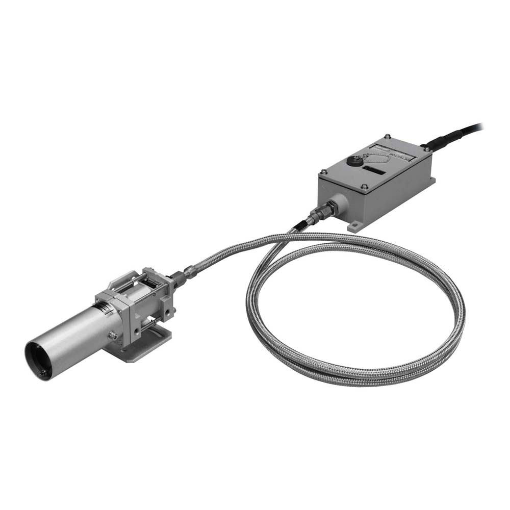
The optical head and amplifier are connected with a fiber optic cable and the infrared ray captured with the optical head is transmitted through highly transmissive glass fiber into an amplifier installed at a distant location. The infrared ray transmitted into the amplifier is optically converted in the light sensitive element and amplified for control signal output (mini power relay, signal relay or
solid state output).
Sensors for low temperature (FD300A Series) and medium/high temperature (FD600A Series) are available.
- No cooling required
The optical head integrating hood and optical lens and fiber optic cable have no electronic component, which allows use in ambient temperature of up to 200 C without cooling. - Excellent durability
Reliable design with the hood and optical head made of metal, fiber optic cable covered with flexible stainless steel braid and metal cased amplifier provides robustness and resistance to heat and corrosion. - 5 point level indicator
Received light intensity is indicated at 5 levels, offering easy viewing of stability. - Self check feature integrated (SAFETY feature)
Operation can be checked with external signal.
Stability check feature is provided, which outputs alarm signal (SAFETY ALARM) when there is not much margin in the received light intensity level at detection due to soiling of lens, light axis misalignment, etc. or external disturbing light or residual heat. - Two types of detection field of view
Standard vew (dia.50mm/m) and Wide view (200x40mm/m, 400x30mm/m) are available.
Dimension
Amplifier unit
Fiber optic cable
Circuit
Control output
SAFETY ALARM output (all models)
When connecting an inductive load such as relay, be sure to use diode, surge absorber, etc. to protect output transistors from counter electromotive force.
Connection
- When connecting an inductive load such as relay as the load, be sure to use diode, surge absorber, etc. for protection of output transistor from back electromotive force.
- When the leads are extended (100-300 m), stray capacitance between leads may cause rush current. If this poses any problem, provide a resistor (10-50 Ω) in series with the contact.
- Ground from frame
Connect to the ground screw (M4) near the connector. You do not have to connect when already connected to the ground Pin.1 with a cable.
Option
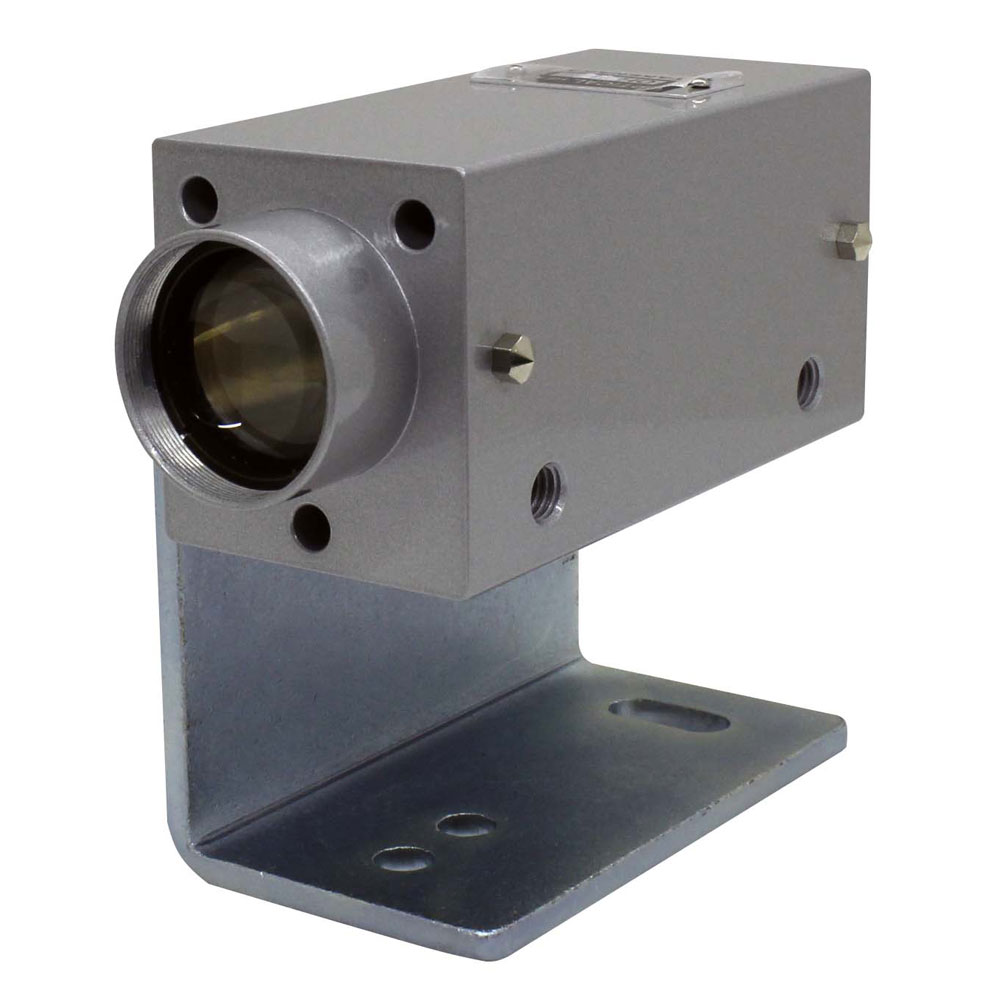
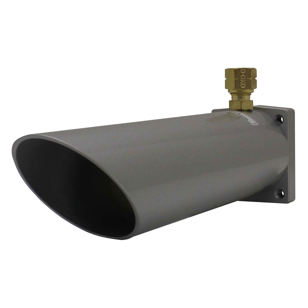
Optical head
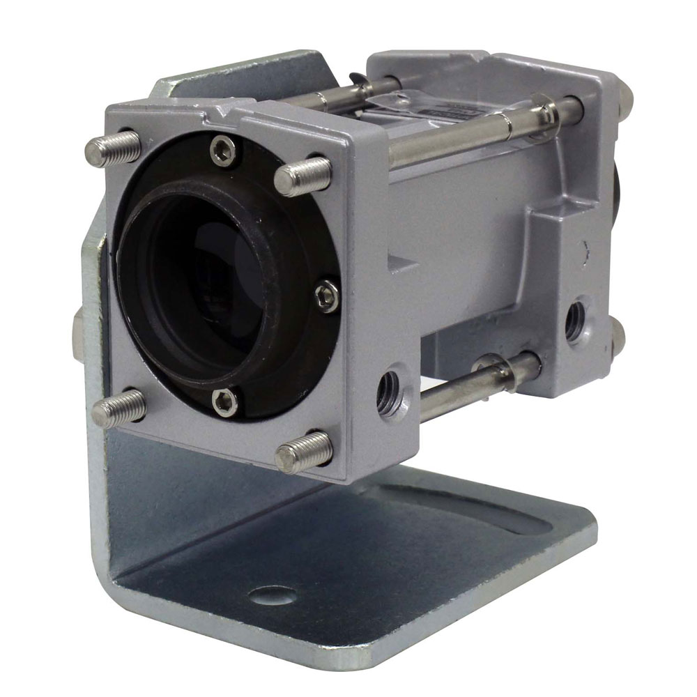
| Optical headOHA |
|
||
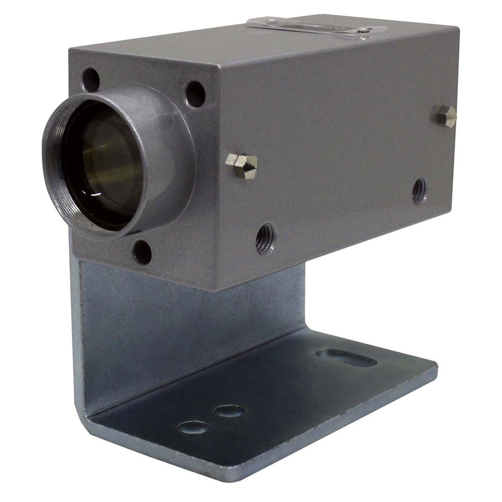
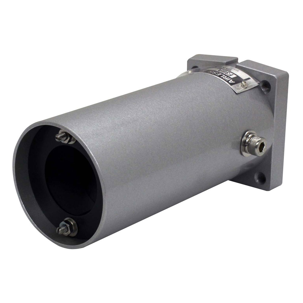
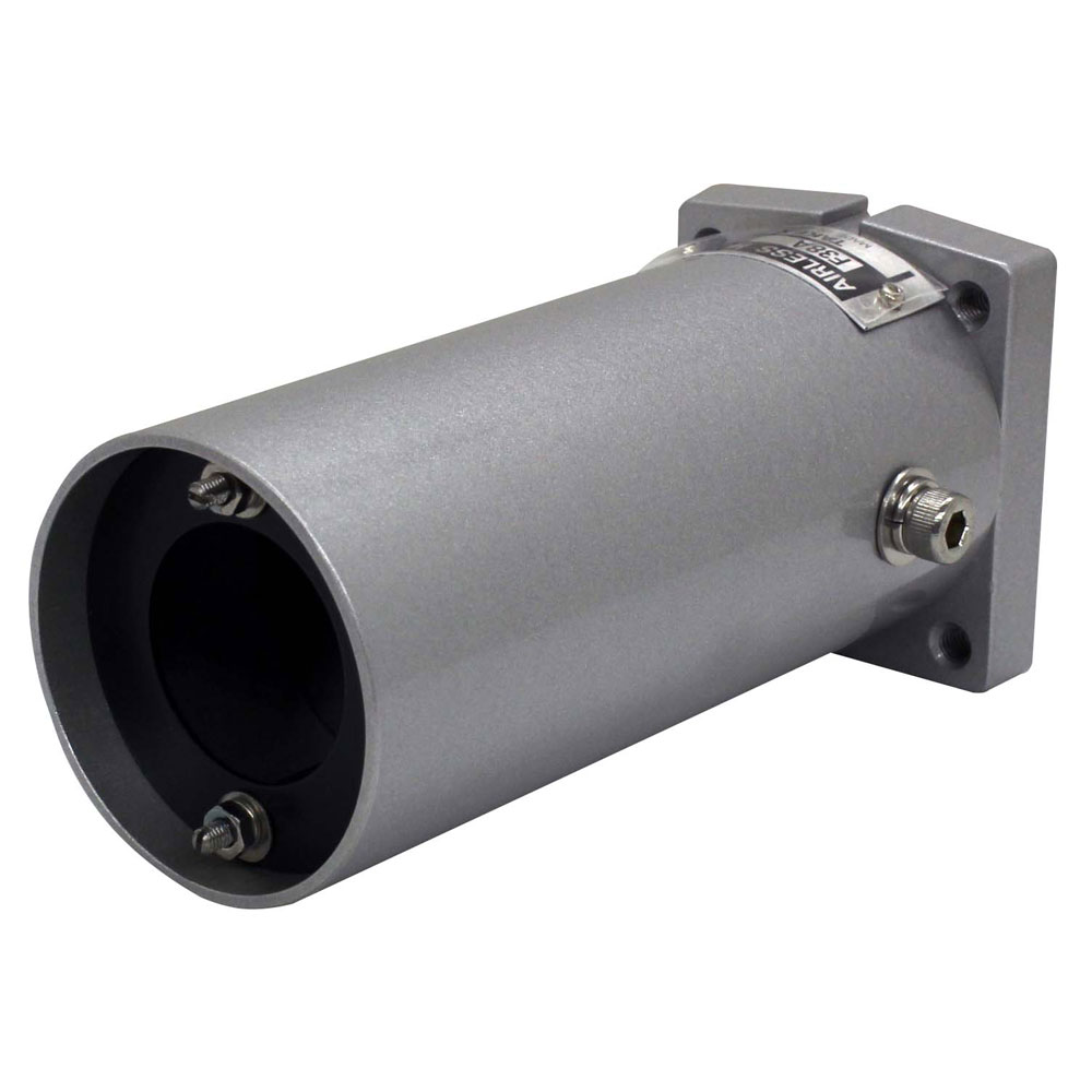
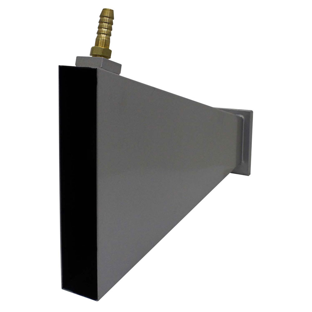
| Optical headOHW1 |
|
||
| Optical headOHW2 |
|
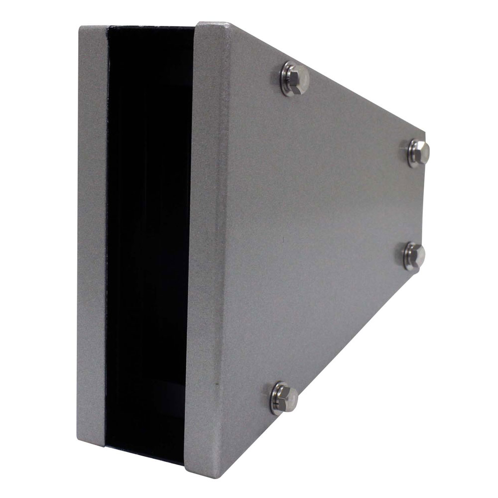
Hood
| HoodF38A |
|
||||||
| HoodF38A-02 |
|
||||||

| HoodF38A-03 |
|
||||||

| HoodF38A-04 |
|
||||||

| HoodF38A-05 |
|
||||||
| HoodF38W |
|
||||||

| HoodF38PC-02 |
|
||||||

| HoodF38PC-03 |
|
||||||

| HoodF38PC-04 |
|
||||||
| HoodF38PC-05 |
|
||||||
| Hood302W |
|
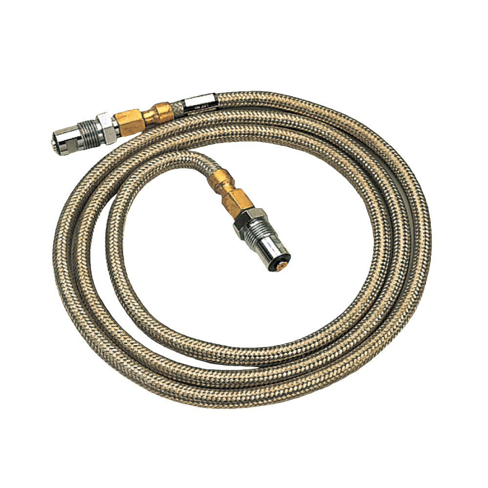
Fiber optic cable

| Fiber optic cableFG2 |
|
||||

| Fiber optic cableFG3 |
|
||||

| Fiber optic cableFG4 |
|
||||

| Fiber optic cableFG5 |
|
||||
| Fiber optic cableFG7 |
|
||||

| Fiber optic cableFG10 |
|
||||

| Fiber optic cableFG15 |
|
||||

| Fiber optic cableFG20 |
|
||||

| Fiber optic cableFG30 |
|